
Going to work down under up front for a better handling Corvette
text by John Pfanstiehlphotography by Chuck James
 ast month we showed
step-by-step removal of our project '73 Corvette's rear suspension components
for rebuilding. Because the Corvette rear suspension was one of the first U.S.
independent rear suspensions, and therefore radically different from the solid
axle suspension Detroit had been producing for generations, it had its own
particular problems and needs
ast month we showed
step-by-step removal of our project '73 Corvette's rear suspension components
for rebuilding. Because the Corvette rear suspension was one of the first U.S.
independent rear suspensions, and therefore radically different from the solid
axle suspension Detroit had been producing for generations, it had its own
particular problems and needs
By comparison, the front suspension on 1963-1982 Corvettes is standard Detroit by-the-book: strong, reliable, simple to understand and easy to work on. The only problems (and they are relatively minor) come from putting a big motor in a small car. Some parts are a little more cramped than on a 4,000-pound full-size barge. Heat close to the upper A-frame bushing and oil slung onto the lower right rear A-frame bushing are two common problems.
Van Steel rebuilt the entire suspension, providing one-stop shopping and providing the same standards and finishes on suspension components on all four corners of the car. Whether you do it yourself or send them off, here's the step-by-step procedure to a new, youthful front end.
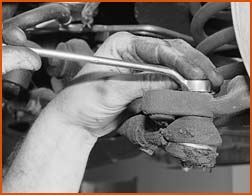
 To
remove the sway bar link, hold the bolt and remove the nut. After the nut,
washers, and cushions are removed, if the bolt will not slide through the
sleeve, it is rusted - seized. The sleeves can be split on their seams to make
removal of the bolt easier.
To
remove the sway bar link, hold the bolt and remove the nut. After the nut,
washers, and cushions are removed, if the bolt will not slide through the
sleeve, it is rusted - seized. The sleeves can be split on their seams to make
removal of the bolt easier.
 Remove
the cotter pins and disconnect the outer tie rod ends from the steering arms.
Note that this tie rod end is in the inner hole on the steering arm. This is the
quick steering or power steering position.
Remove
the cotter pins and disconnect the outer tie rod ends from the steering arms.
Note that this tie rod end is in the inner hole on the steering arm. This is the
quick steering or power steering position.
 Remove the cotter pin and nut from the idler arm. If you are removing all
the suspension components, you don't have to use the tie rod end splitter to
separate the idler arm from the drag link at this point. Instead, unbolt the
idler arm, disconnect the tie rods at the steering arms, and disconnect the drag
link by pulling off the pitman arm.
Remove the cotter pin and nut from the idler arm. If you are removing all
the suspension components, you don't have to use the tie rod end splitter to
separate the idler arm from the drag link at this point. Instead, unbolt the
idler arm, disconnect the tie rods at the steering arms, and disconnect the drag
link by pulling off the pitman arm.
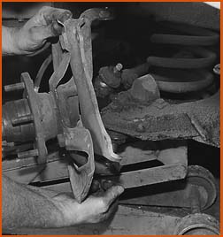
 If you
are splitting the idler arm from the drag link while it is still connected to
the steering box, use the tie rod end splitter at an angle, to prevent putting a
lot of force on the steering box. The idler arm is attached to the frame with
two fine-thread nuts and stove bolts. After removing the idler arm, clean the
bolt threads to make installation easier.
If you
are splitting the idler arm from the drag link while it is still connected to
the steering box, use the tie rod end splitter at an angle, to prevent putting a
lot of force on the steering box. The idler arm is attached to the frame with
two fine-thread nuts and stove bolts. After removing the idler arm, clean the
bolt threads to make installation easier.
Replacement idler arms are available which have roller bearings at both ends. These can be greased; they are much more precise; and they last much longer than the original equipment - rubber bushed idler arms.
Disconnect the upper end of the shock absorber from inside the engine compartment. Typically, a 9/16 wrench or socket will work. If the shaft spins, the upper end of the shaft may need to be held with a small wrench. If the shock absorber is not going to be reused, it might be easier just to use a chisel to cut through the flat on the nut.
Use a half-inch socket or wrench to remove the two bolts which hold the shock absorber on the lower end. Always disconnect the upper end of the shock absorber first.
When removing the caliper, place a spacer between the brake pads to prevent the pistons from coming out too far in the caliper bore; a 15/16 half-inch drive socket works fine for this. The brake rotor can be removed either before or after the spindle assembly is taken from the car. I generally take it off first to make the spindle assembly lighter.
Remove the cotter pins from both upper and lower ball joints. Side cutters work well to bend and pull the cotter pins out. You may have to wipe off the grease to see what you are doing.
Remove the nut on the upper ball joint; a box wrench works best in this area. It is a good idea to leave the nut on a few turns so that when the spindle breaks loose from the ball joint, it won't fall down on you.
The spindle can often be separated from the ball joint by striking it at that location with a large hammer instead of using a ball joint splitter. The one advantage of this method is that the rubber boot won't be damaged.
 After
breaking loose both the upper and lower ball joints, support the A-frame to
compress the spring; finish removing the nut from the upper ball joint; and
remove the spindle assembly.
After
breaking loose both the upper and lower ball joints, support the A-frame to
compress the spring; finish removing the nut from the upper ball joint; and
remove the spindle assembly.
With the spindle assembly out of the way, pry the lower A-frame down to pop out the spring. Note that the frame has to be fairly far off the ground to allow the A-frame to come down sufficiently. Be careful when prying out the spring.
Remove the large nut on the rear end of the lower A-frame shaft and the two bolts on the front end. It will be necessary to hold the bolt while removing the large nut. Use a 13/16-inch wrench and a 7/8 socket. The front bolts can be removed with a 5/8 wrench or socket.
Remove the two nuts which secure the upper A-frame shaft to the frame; a ratchet wrench helps in these tight quarters. Oiling the exposed threads or cleaning them with a wire brush may also help.
It may be necessary to remove one or more of the studs. To accomplish this, tap them outward or use a slide hammer with an attachment, as shown here.
Removal of the upper A-frame is accomplished through the inner fender into the fender well.
 After
the A-frame is removed, use a drill or chisel to cut off the heads of the two
rivets on the lower ball joints.
After
the A-frame is removed, use a drill or chisel to cut off the heads of the two
rivets on the lower ball joints.
After removing the rivets, use a 3/4-inch socket or wrench to remove the upper nut and remove the old ball joints.
After removing the bushing bolt, lock washer, and large washer, the A-frame bushing can be popped out of the A-frame using a dull chisel or air chisel.
The three rivets holding the upper ball joint are also removed by chiseling or drilling off the heads. Note that in the Corvette's suspension, the weight is carried by the lower ball joints. They wear out much faster than the upper ball joints. You may find that the upper ball joints are in excellent condition even after 200,000 miles.
 After removing the dust cap and spindle nut, the hub assembly can be removed
from the spindle. Note: If your rotor is still riveted to the hub assembly, it
won't look like this! The rotors were originally riveted to the hubs and the
rivets should be removed only for rotor replacement.
After removing the dust cap and spindle nut, the hub assembly can be removed
from the spindle. Note: If your rotor is still riveted to the hub assembly, it
won't look like this! The rotors were originally riveted to the hubs and the
rivets should be removed only for rotor replacement.
The rear view of the spindle assembly shows the two nuts which hold the steering arm and the caliper mounting bracket to the lower end of the spindle.
After removing the nuts and bolts which secure the steering arm to the bottom of the spindle assembly, remove the large upper bolt which holds the caliper mounting bracket and dust shield to the spindle.
The spindle assembly looks a lot better after cleaning and refinishing. It is important to check the bearing surfaces and the seal surfaces of the spindle to make sure they don't show excessive wear. Installation of the rebuilt parts is straight-forward, just a reversal of the disassembly operation. Note that the upper-frame is painted black, while the ball joint is not.
If the studs which secure the upper A-frame shaft were removed, place the upper A-frame in position, insert the studs through the frame and the shaft, and tap them firmly into place.
Installation of the A-frame is easier if the bushing bolts are not tightened. This permits the A-frame to swing down and out of the way for better access to the bolts and nut. In addition, it is better not to tighten the bushing bolts until the suspension is sitting at riding height so there is minimal strain on the rubber during normal operation.
The shaft on the shock absorber should be pulled out to its fullest length (this won't be necessary with air shocks). The bolt is inserted through the lower A-frame. Be careful not to over-tighten the bolts that hold the lower end of the shock to the A-frame because they are only 5/16-inch diameter and don't require much torque.
After installing the caliper on the rotor, make sure that there are no kinks in the brake hose. To do this, install the hose into the frame bracket only after it has been tightened on the caliper. It is a good idea to turn the steering all the way left and all the way right to make sure that the hose does not kink, and to make sure that it will not touch the frame when the A-frame moves up.
 Installation of the sway bar links is one of the last steps.
Note that the original nuts were non-standard using a 9/16 wrench, while most
replacement nuts use a 1/2-inch wrench. The bolts should be inserted from the
bottom with the nut on top. Also note that the washers cup the bushings.
Installation of the sway bar links is one of the last steps.
Note that the original nuts were non-standard using a 9/16 wrench, while most
replacement nuts use a 1/2-inch wrench. The bolts should be inserted from the
bottom with the nut on top. Also note that the washers cup the bushings.
The suspension is all bolted together and awaiting installation of the wheels - ready for another 100,000 miles! It looks like new and rides like new, too!

For a complete version of this story in print, look for Corvette Fever on your local newsstand.


Copyright(c) 1997: Dobbs Publishing Group.